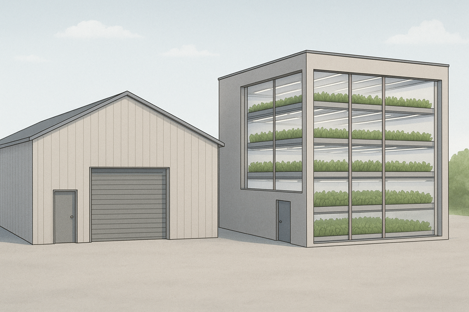

Designing a successful vertical farm requires careful consideration of how much weight a structure can safely carry. Load-bearing consideration for vertical farming racks is a matter of engineering efficiency and is central to crop safety, worker protection, and long-term operational reliability. When farms are built inside warehouses, shipping containers, or purpose-built facilities, the entire cultivation system rests on the strength and stability of the load-bearing framework. This includes the racks that hold plants, the floors that support irrigation and lighting, and the building envelope itself. A miscalculation in load-bearing capacity can result in costly failures, ranging from equipment damage to risks for human safety. For this reason, understanding the fundamentals of structural loading is essential for anyone involved in planning or operating indoor farms.
Why Load-Bearing Matters in Controlled Environment Agriculture
Vertical farming differs from conventional agriculture because crops are stacked in tiers, often supported by steel or aluminium racks. Each tier holds trays of plants, nutrient solution, growing medium, and integrated equipment such as LED lighting and irrigation pipes. The combined weight of these elements is significantly greater than that of traditional single-layer cultivation. For example, a single hydroponic tray system can weigh between 30 and 60 kilograms when filled, and when multiplied across multiple levels, the total load quickly escalates. The structure must therefore be designed to support both static loads, which are the constant weights of plants and equipment, and dynamic loads, which arise from water movement around the systems (the size of which will depend on the irrigation approach selected), worker access, movement of carts, and the gradual increase of crop weight due to growth.
Ignoring these principles can create uneven stress across racks, cause bending or buckling of beams, and even compromise the building floor slab. In older facilities that were not originally intended for agricultural use, such as converted warehouses, this is a particular concern. A clear understanding of load-bearing principles ensures that the farm remains safe, efficient, and scalable.
Structural Design Principles for Indoor Farming Racks
Load-bearing farm design for vertical farming racks follows established engineering practices, adapted to the unique demands of plant production. The key factors considered by structural engineers include the type of material used in the racks, the spacing of vertical supports, and the maximum permissible load per square metre. Steel is often favoured for its strength-to-weight ratio, while aluminium offers corrosion resistance and lighter handling. Wooden racks are rarely recommended in professional facilities due to limited durability and moisture-related deformation.
The design must account for both uniformly distributed loads, such as evenly spaced trays, and point loads, which occur when heavy equipment is positioned on a small area. Engineers typically calculate a safety factor, adding a margin above the expected load to account for variations in operation. For example, a rack designed to carry 500 kilograms per shelf might be specified with a capacity closer to 650 kilograms to ensure resilience. Floors are equally important: in multi-storey farms, floor slabs must be engineered to carry concentrated rack loads without cracking.
Environmental Considerations Affecting Load
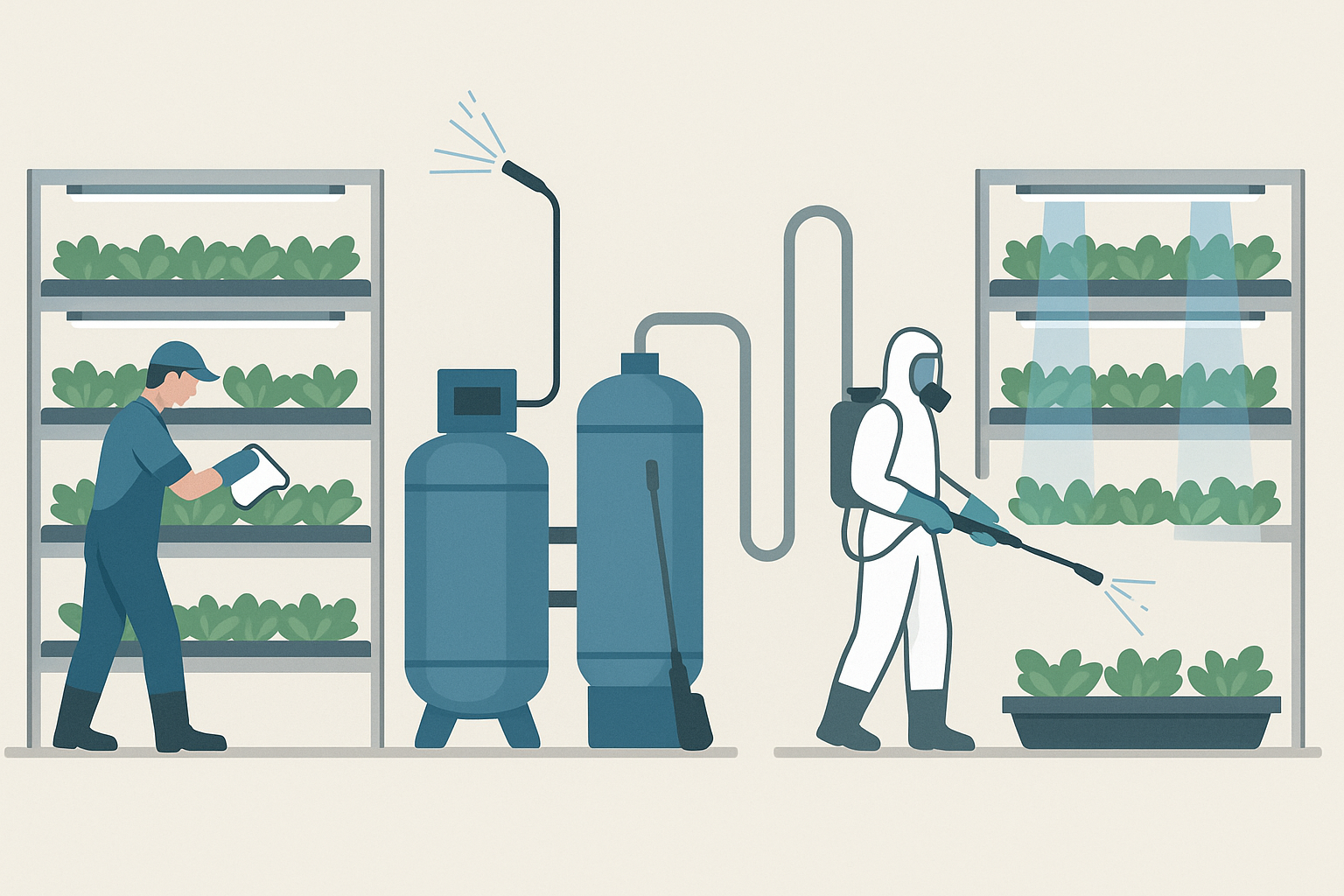
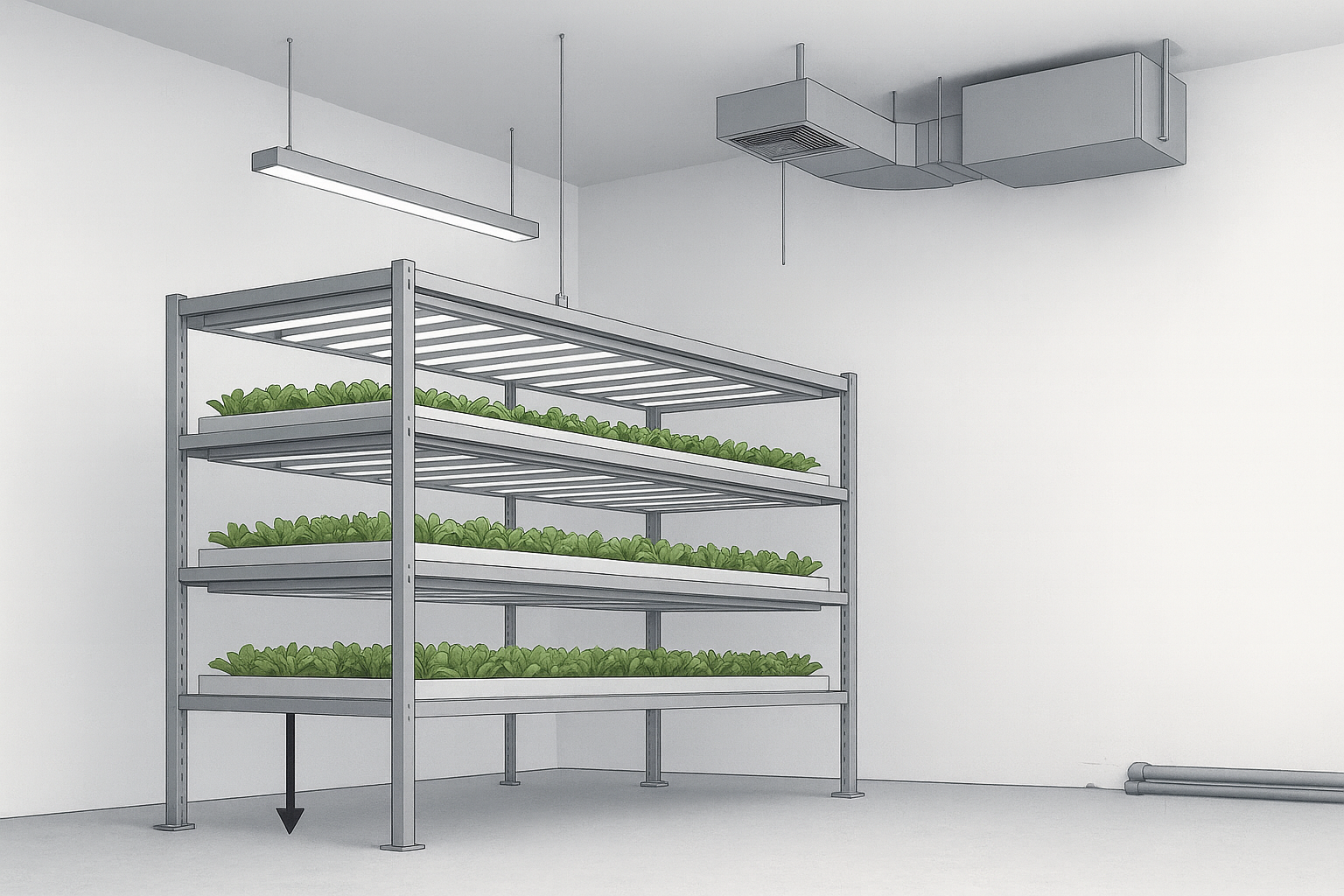
Indoor farms operate under conditions that place additional stress on structures. High humidity and constant water circulation can cause corrosion if materials are not properly treated. In hydroponic or aquaponic systems, water tanks and circulation pipes add substantial weight, and any leakage can create both safety hazards and uneven load distribution. Furthermore, HVAC systems and ducting suspended from ceilings add overhead loads that must be factored into the overall design.
Lighting infrastructure, while relatively light in isolation, contributes meaningfully when extended across entire farms. Similarly, workers climbing ladders to service upper tiers introduce live loads that shift over time. These environmental and operational factors mean that load-bearing calculations for vertical farms must extend beyond the static weight of plants and trays to encompass the dynamic realities of farming indoors.
Examples of Load-Bearing Challenges in Practice
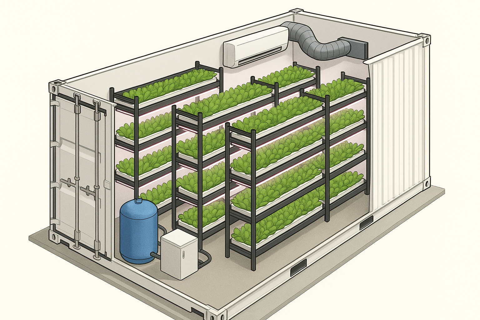
Real-world experiences illustrate the importance of proper design. In several early vertical farm conversions, operators underestimated the weight of water-filled systems, leading to sagging floors or the need for expensive retrofits. A facility using aeroponic towers discovered that while the individual units were lightweight, the combined mass of water reservoirs created unexpected stress on a mezzanine floor. Another example can be found in container farming: although containers are structurally strong, modifications such as cutting doors or adding HVAC systems can weaken load distribution, requiring reinforcement. These examples show that even small oversights in load-bearing assessment can lead to operational and financial setbacks.
Integrating Load-Bearing Design with Farm Planning
Addressing load-bearing is not an isolated engineering task but a key part of overall farm planning. Collaboration between agricultural designers, architects, and structural engineers is essential. Early modelling using software can simulate how racks, water tanks, and equipment will distribute loads across the facility. This not only reduces the risk of structural failure but also allows for optimisation of rack arrangement and workflow. For investors, demonstrating that a facility has been professionally assessed for load-bearing is often a condition for securing funding or insurance.
Ultimately, load-bearing farm design for vertical farming racks provides the foundation upon which crop yield, efficiency, and safety depend. As vertical farming scales up, with multi-storey buildings and increasingly heavy automation systems, the demand for rigorous load-bearing standards is likely to grow. By treating load-bearing as a central design principle rather than a secondary technical detail, growers and planners can build farms that are safe, efficient, and capable of long-term operation.
DIY Science!
The following is a concise, engineering-style walkthrough of how to calculate load bearing for a vertical farming rack, for those that like to understand a process in detail. It covers the key equations, the sequence of checks, and offers a worked example that you can adapt to your own geometry and materials - but this should not be considered as a blueprint for emulation. For this, you need to seek professional help! Nevertheless, a little knowledge and insight is power, so hopefully the below gives some idea of expected complexity.
Defining the problem and inputs
A rack is a structure made of shelf beams spanning between uprights. Each shelf carries plants, water, trays and lights, fans, and other potential equipment. Loads are either uniformly distributed along a shelf or concentrated at points. You must know: span L of the shelf beam; shelf load per unit length w (N/mm or kN/m); any point loads P (kN); material properties E (Young’s modulus) and yield strength f_y; shelf beam section properties: second moment of area I and section modulus S; upright height and effective length factor K; base plate size; floor capacity.
Shelf beams: bending, shear and deflection
For a simply supported shelf beam with a uniformly distributed load w:
Maximum shear:V_max = w L / 2
Maximum bending moment:M_max = w L^2 / 8
Mid-span deflection:delta = 5 w L^4 / (384 E I)
For a central point load P on a simply supported beam:
V_max = P / 2M_max = P L / 4delta = P L^3 / (48 E I)
Bending stress check:
sigma_b = M_max / S
This must be less than the permissible bending stress. A common first pass is sigma_b <= f_y / gamma_M; gamma_M is a material factor set by your design code. Serviceability deflection is usually limited to L/200 to L/300 for steel shelving; adopt a project limit, for example delta <= L/250.
Shear stress in thin shelf members can be estimated conservatively as:
tau_v = V_max / A_v
where A_v is the effective shear area of the web. Ensure tau_v is below the allowable shear stress.
Uprights: axial capacity and buckling
Total vertical load from all shelves and attachments is shared by the uprights. For n uprights:
N_upright = (sum of shelf reactions + self-weight) / n
Check axial stress:
sigma_c = N_upright / A
where A is the cross-sectional area of the upright. Because uprights are slender, include buckling. A simple elastic buckle capacity is:
P_cr = pi^2 E I_c / (K L_c)^2
where I_c is the least second moment of area of the upright, L_c is its clear length between restraints, and K is the effective length factor that reflects end restraint conditions. In code-based design this becomes a design resistance:
N_Rd = chi A f_y / gamma_M
where chi is a reduction factor obtained from a buckling curve that depends on slenderness. Ensure N_upright <= N_Rd.
Base plates and floor bearing
Bearing pressure under a base plate:
q = N_upright / A_plate
Ensure q does not exceed the allowable bearing of the floor slab or the point load capacity at the rack foot. If necessary, use larger plates or spreader rails to reduce q. Also verify anchors for shear and uplift if seismic or impact loads apply.
Load combinations and safety factors
Include all relevant actions: dead load G (equipment; water; structure); imposed load Q (workers; mobile carts); any lateral actions such as seismic or accidental impact from trolleys. Apply the partial factors and combinations required by your governing standard. A common service combination for deflection is G + Q. A common ultimate combination is gamma_G G + gamma_Q Q; use your code’s values.
Worked example: four-tier hydroponic rack
Assumptions: steel shelves spanning between uprights; span L = 2.4 m; per-shelf uniformly distributed load w = 1.2 kN/m (plants; trays; water; lights); E = 200 GPa; steel yield f_y = 275 MPa; two beams per shelf acting compositely as one equivalent beam is assumed for simplicity; four uprights; clear upright height L_c = 2.5 m; base plate 100 mm x 100 mm; target deflection limit L/250.
Convert units for beam checks: L = 2400 mm; w = 1.2 kN/m = 1.2 N/mm.
Shear per shelf:V_max = w L / 2 = 1.2 * 2400 / 2 = 1440 N
Moment per shelf:M_max = w L^2 / 8 = 1.2 * 2400^2 / 8 = 0.864 kN m = 864,000 N mm
Required section modulus from bending stress, taking an allowable bending stress of 160 MPa as a first pass (for example f_y / gamma_M with gamma_M about 1.7):
S_req = M_max / sigma_allow = 864,000 / 160 = 5,400 mm^3
Serviceability deflection with a trial I: suppose the beam depth gives c = 25 mm; with S = 5,400 mm^3, I = S c = 135,000 mm^4.
Predicted deflection:delta = 5 w L^4 / (384 E I)= 51.22400^4 / (384200,000135,000)= 19.2 mm
Deflection limit L/250 = 2400 / 250 = 9.6 mm. The trial section is too flexible. Solve for I required:
I_req = 5 w L^4 / (384 E delta_allow)= 270,000 mm^4
If c remains near 25 mm, the corresponding section modulus is S = I_req / c = 10,800 mm^3. Select a shelf member with S >= 10,800 mm^3 and I >= 270,000 mm^4; recheck bending and deflection with the actual catalogue values.
Total gravity load per shelf is w L = 1.2 kN/m * 2.4 m = 2.88 kN. Four shelves give 11.52 kN. Add 1.0 kN for rack self-weight and services: total 12.52 kN. Reactions are shared by four uprights:
N_upright = 12.52 / 4 = 3.13 kN
Axial stress with an upright area A = 300 mm^2:
sigma_c = 3,130 N / 300 mm^2 = 10.4 MPa, which is modest; buckling governs the design. With L_c = 2.5 m and a conservative K = 1.0, you must verify that the upright’s design buckling resistance N_Rd exceeds 3.13 kN with adequate margin using your code’s buckling curve and the upright’s weakest-axis I_c. In practice, standard pallet-rack uprights comfortably exceed this, but do not assume: check the manufacturer’s capacities at your shelf spacing.
Base plate bearing with a 100 x 100 mm plate:
A_plate = 0.1 m * 0.1 m = 0.01 m^2q = 3.13 kN / 0.01 m^2 = 313 kN/m^2
If the slab’s allowable concentrated bearing is lower than this value, increase plate area or place the rack on continuous rails to spread the load.
Practical notes
Use the real self-weight of water: 1.0 litre = 1.0 kg. Include the extra mass of saturated media and drainage retention. Treat workers on upper tiers as live load; a simple allowance is 1.5 to 2.5 kN locally per bay during maintenance. Check lateral stability with bracing or fixed bases. Where shelves are not simply supported, or where beams are built from cold-formed sections with perforations, use manufacturer test data or a code method for perforated members; section properties and capacities can differ from plain-web theory.
Summary of the calculation sequence
Quantify shelf loads; compute shear, moment and deflection using the beam equations above; size shelf members so that sigma_b <= allowable and delta <= serviceability limit. Sum shelf reactions to find upright loads; check axial stress and buckling capacity. Verify base plate bearing and anchors; confirm floor capacity. Apply the correct load combinations and material factors from your governing standard, then document assumptions and margins.